

🔔 Important Update: U.S. Tariff Policy Change in 2025 U.S. orders will include tariffs. Click here to learn more on our Blog.


- Vendor: KittenBot
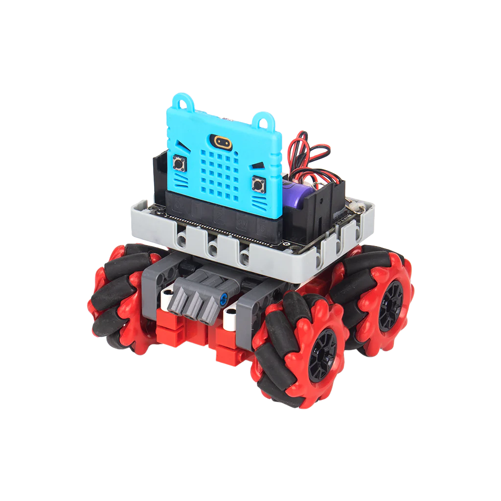
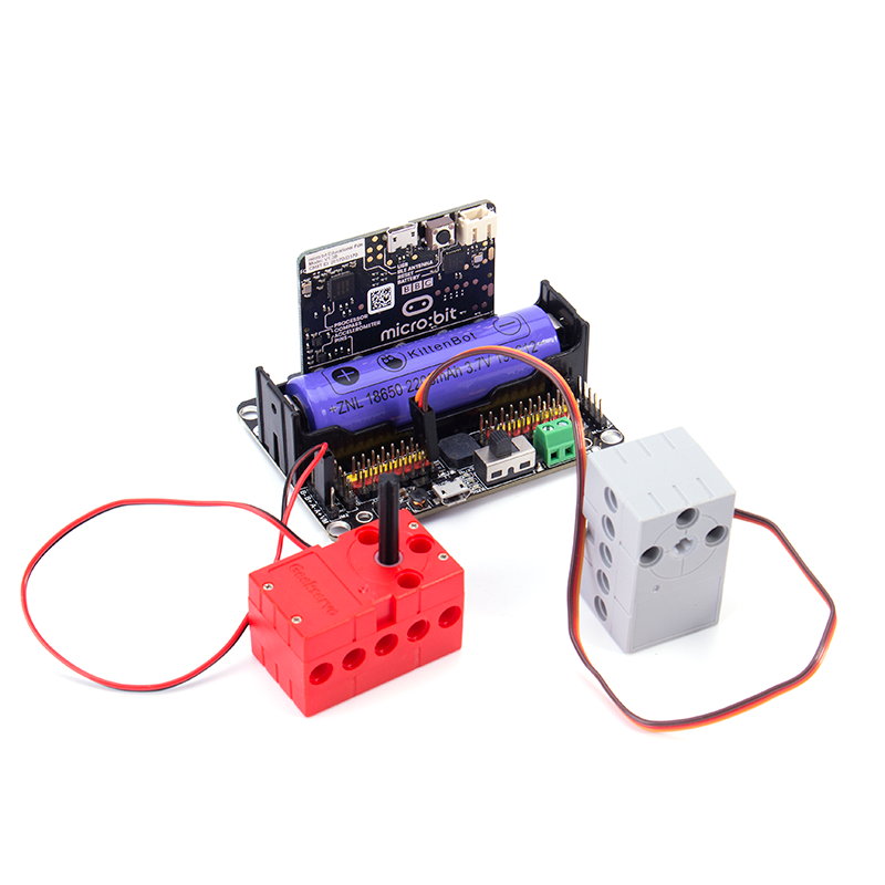
KittenBot Robotbit Robotics expansion board for micro:bit
$19.90 USD
Tax included.
Shipping calculated at checkout.
In stock!


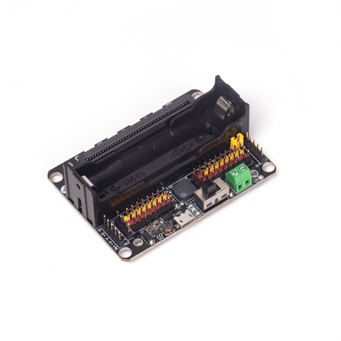
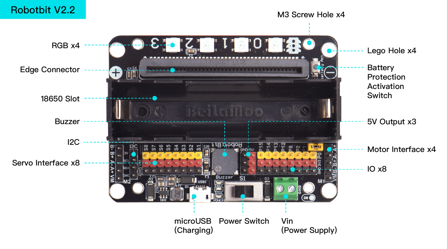
 Hardware Resources
- 5V external power input(with anti-reverse protection)
- Power switch
- Power Indicator
- Battery Indicator
- Micro USB charing port
- 4-channel DC motor / 2-channel stepper motor
- Jumper for buzzer selection
- 8 channel IO(corresponding to Micro:bit P0-P2、P8、P12-P15)
- 5V and GND port
- Buzzer
- 8 channel servo port
- I2C interface (expandable I2C module)
- 18650 battery case
- Bettery protection recovery push button
- Micro:bit edge connector
- 4x RGB pixel
- Servo driver (PCA9685)
- 2xDc/Stepper driver (DRV8833)
- KittenBot robot chassis mounting hole
- Standard LEGO hole
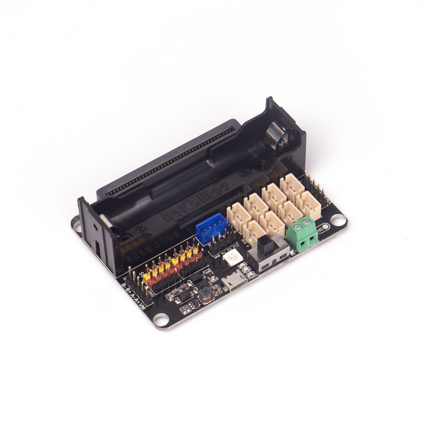
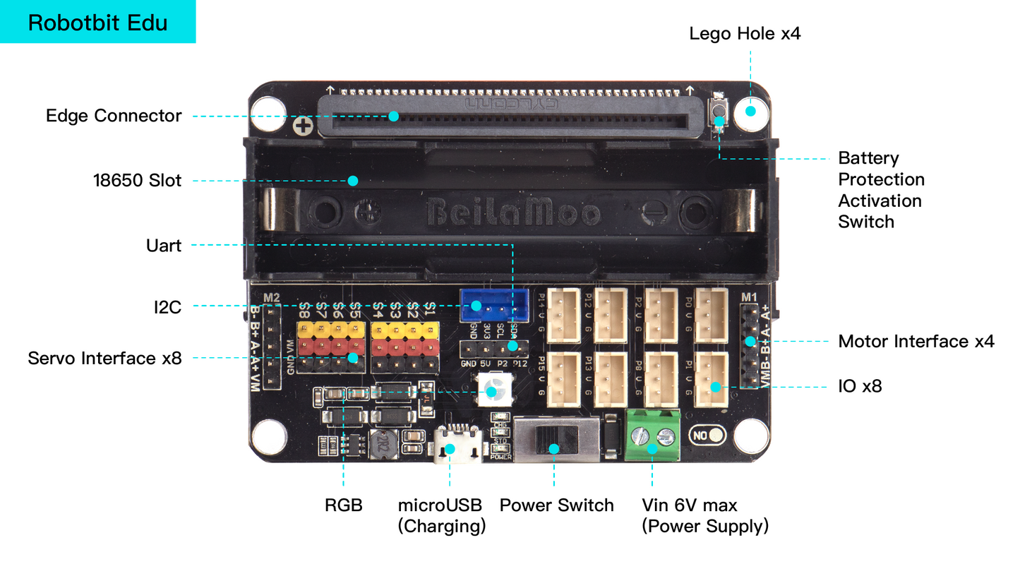
Version Comparison
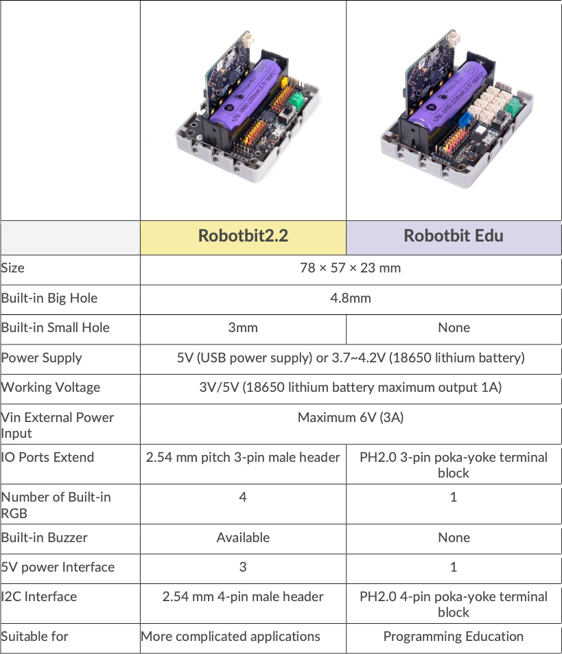
More about Robotbit Edu, go to here
Have a question?
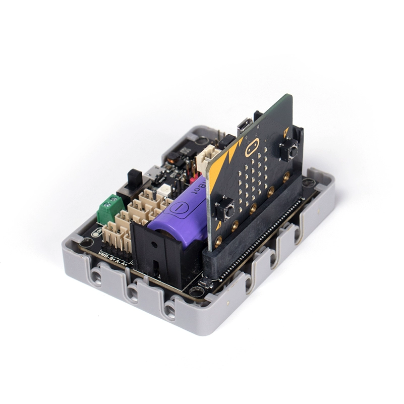
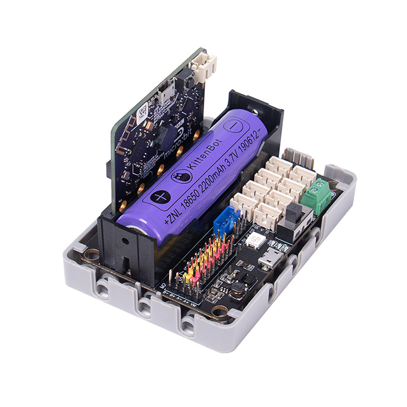
KittenBot Robotbit Robotics expansion board for micro:bit