

🔔 Important Update: U.S. Tariff Policy Change in 2025 U.S. orders will include tariffs. Click here to learn more on our Blog.


- Vendor: KittenBot
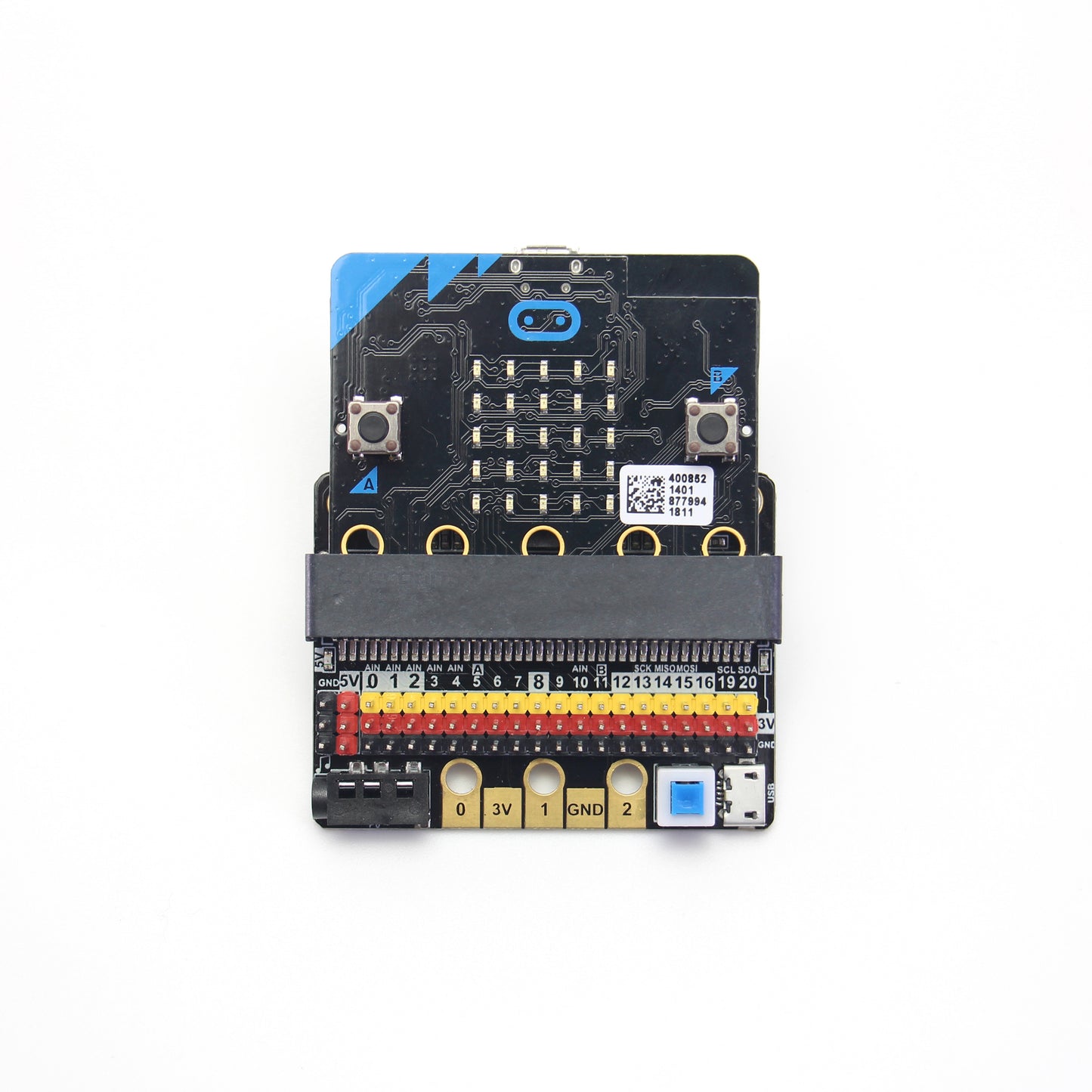
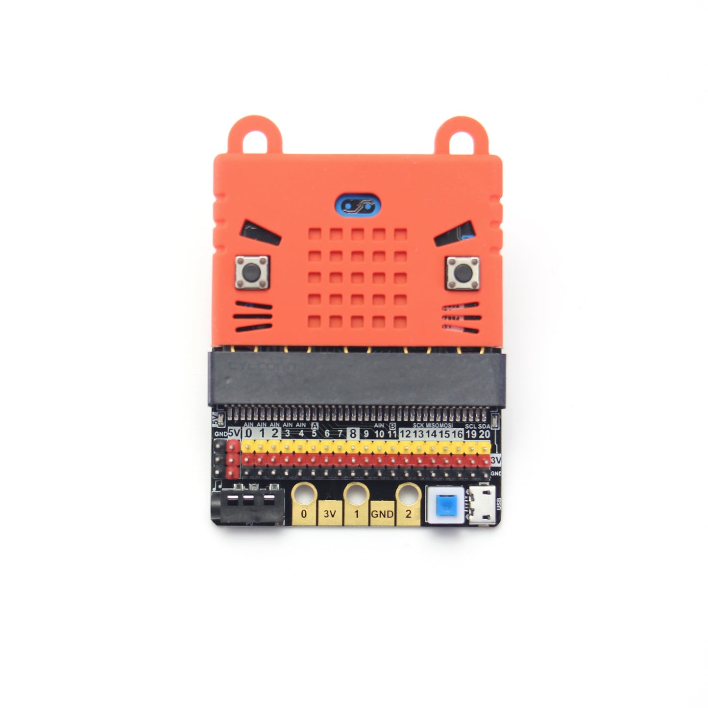
KittenBot IOBIT V2.0 for micro:bit


IObit, IO refers to (input, output), IObit as seen from the name is mainly to serve as pin outputs. It's suitable for some DIY enthusiasts hoping to use all of the IO ports.
Shipping
IObit 2.0 X1
Introduction
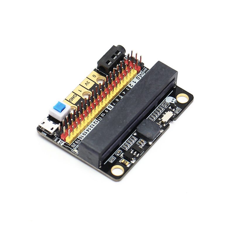
This is a low-cost expansion board for Micro:bit, which is specifically used for the IO ports of Micro:bit. It has taken all the IO resources on the Micro:bit, and also has a buzzer on the board. It is connected to the P0 pin through the jumper cap. The P0 pin can be released using a jumper cap. The small size is very suitable for small projects using Micro:bit.
Features
- Small size, very suitable for DIY
- All IO ports are extracted
- On-board buzzer- you can directly use the music module in MakeCode to play music. At the same time, the 3.5mm audio connector on the board can be connected to audio equipment; such as, headphones to have more creative endeavors.
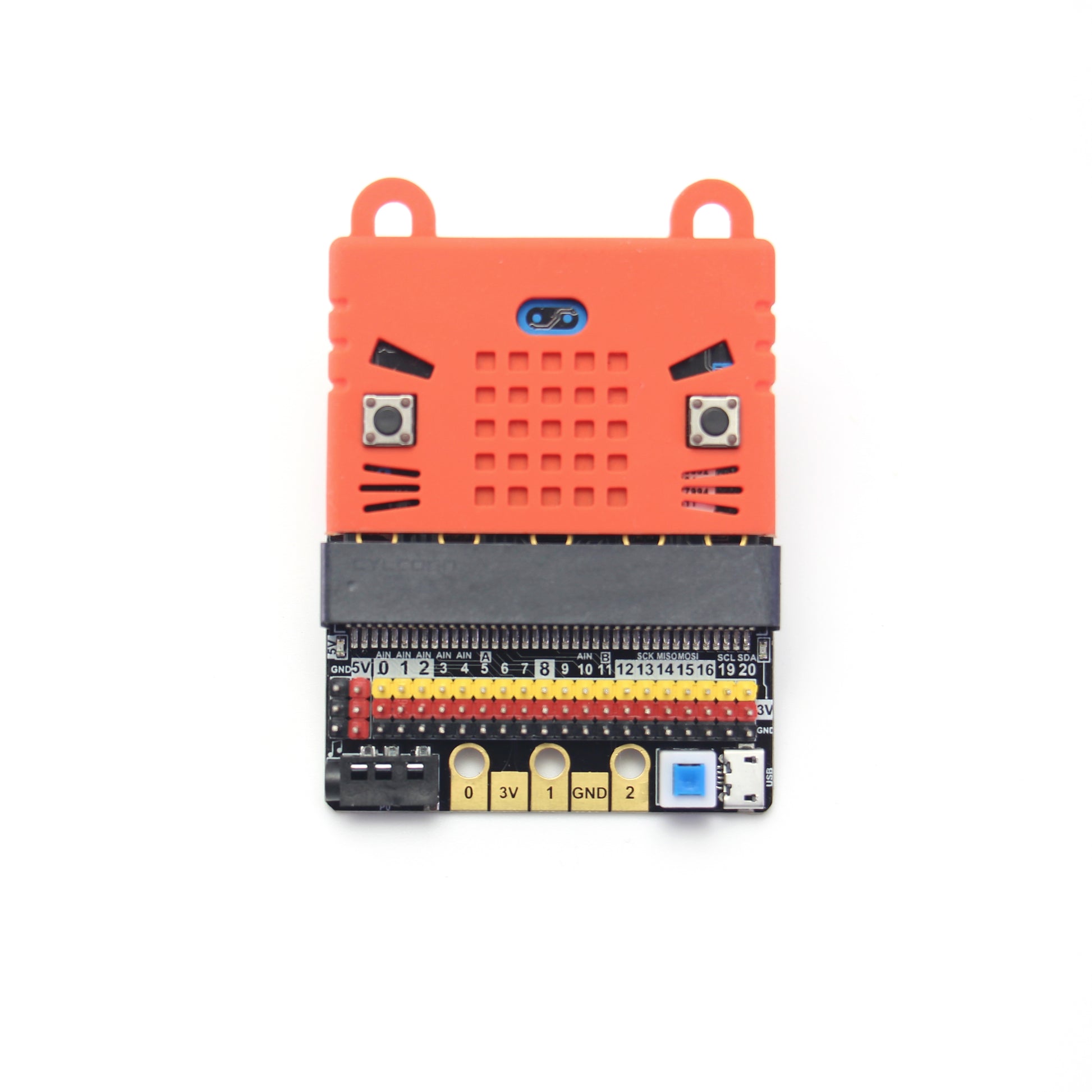
- Two LEGO-compatible pin holes for easy assembly and integration
- The 3PIN interface is distinguished by yellow, red, and black. It is created so that plugging it in the wrong way is difficult, and it is convenient to plug in the sensors.
- It imitates the 5PIN gold fingers on the Micro:bit. This is convenient for makers who like to use the alligator clips.
- Compared with IObit1.0, the biggest difference is that it can input and output 5V, support 5V sensor use, and increases the drive capacity (can drive multiple 9g small servos).
- Includes 1A self-recovery fuse
- Custom-designed silk screen board
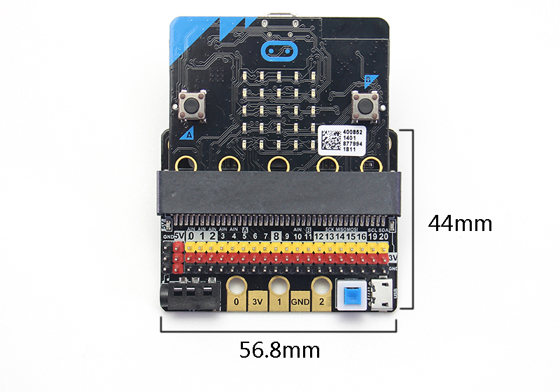
Product parameters
Length x width x height: 57mmx44mmx12mm
Technical parameters
- Power supply mode: IobitV.2.0 supports USB5V power supply. This power supply mode requires pressing the blue power switch.
- Working voltage: 3V-5V (5V sensor module is not supported under 3V power supply)
- Output current: 3V and 5V power interface with maximum output 1A
-
Serial port extraction: serial port can map IO port

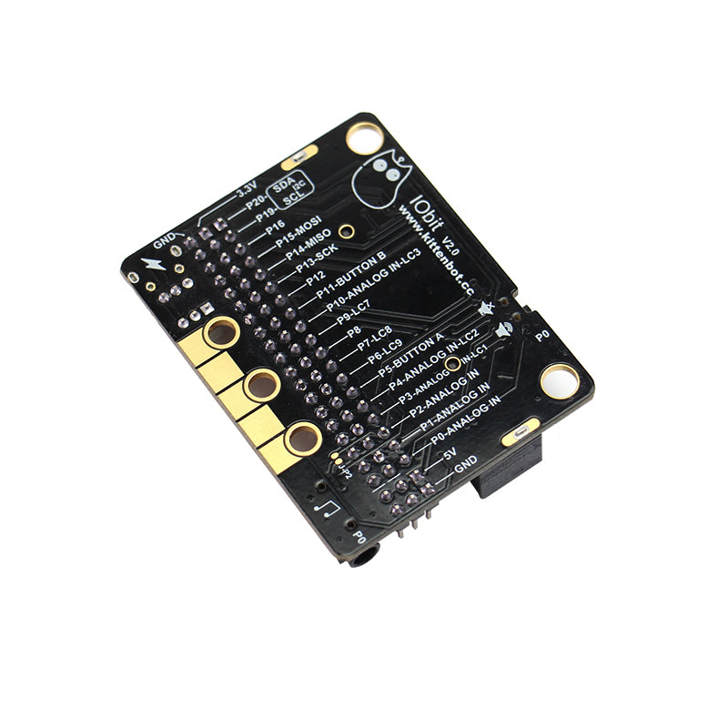
- I2C port leads: pins 19 and 20 can only be used as I2C function pins. They cannot be read and written as ordinary IO ports, because Micro:bit bottom is dead.
- Spi port leads; 14, 15 (IO port can be read and written).
Programming:
Specifics:
It is consistent with Micro:bit programming, because IObit does not have its own drive chip (except buzzer). The building block that is generally used with IObit is to operate the IO port. Many sensors on the market return a high and low voltage. Flat, or an analog value. For actuators, the microbit needs to output high and low level to control. People who are not familiar with this aspect can search Netease Cloud Classroom: Xiaoyan Technology and find the arduino tutorial, which explains how to use the commonly used sensors on the market, the principle is the same.
Before using the building blocks, you must first understand the control method or reading method of the electronic module you are using. 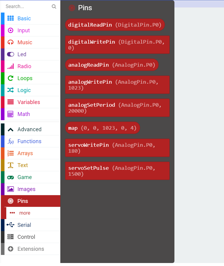
Digital reading
Most newbies will fall out of here because they often ignore setup pull-ups or pull-downs during initialization. So the level state will fail after reading it once. Therefore, we must pay attention to this. Micro:bit itself does not help to set up and down by default, you need to set it yourself. 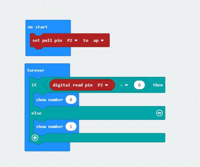
Analog reading
In response to the analog reading, because the analog reading will return a value of 0-1023, it is always inconvenient to display it with a dot matrix screen. So here we take advantage of the unique serial port debugging function of the MakeCode offline version produced by Xiaoyan. First, download the program shown in the figure to open the serial port. In step 2, the console of the device will appear, you can see the data returned in real time. 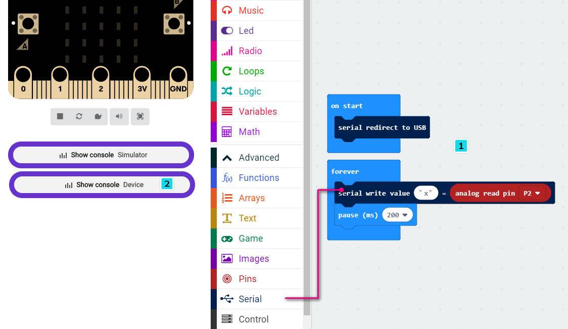
Digital writing
Digital read here does not need to set up and down
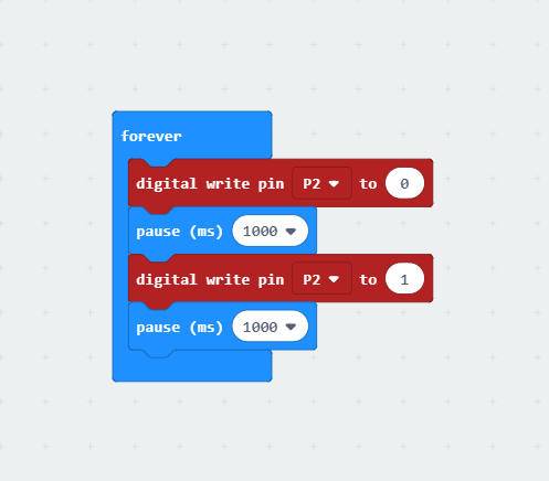
Analog write
Simulated writing an example of a flashing light
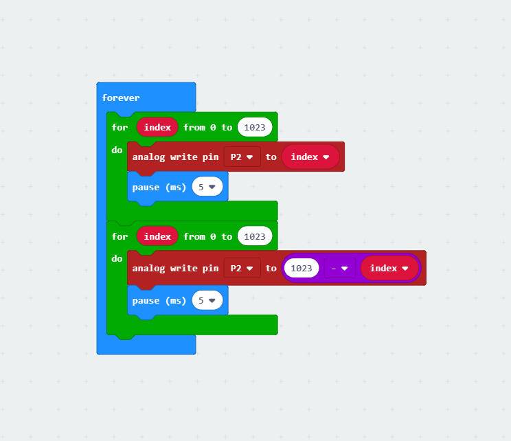
The most commonly used IO port operation is one of these four types. After you master it, you should have no problem with the commonly used sensors on the market. Another thing to note is that the sensors on the market are 5v and 3.3V compatible. But some can only work in 5V. For example, the blue ultrasonic wave that Taobao sells can ordinarily only work in 5V. If IObit is connected, the number read back will always be 0, because the module is not working properly!
Introduction to IObit hardware:
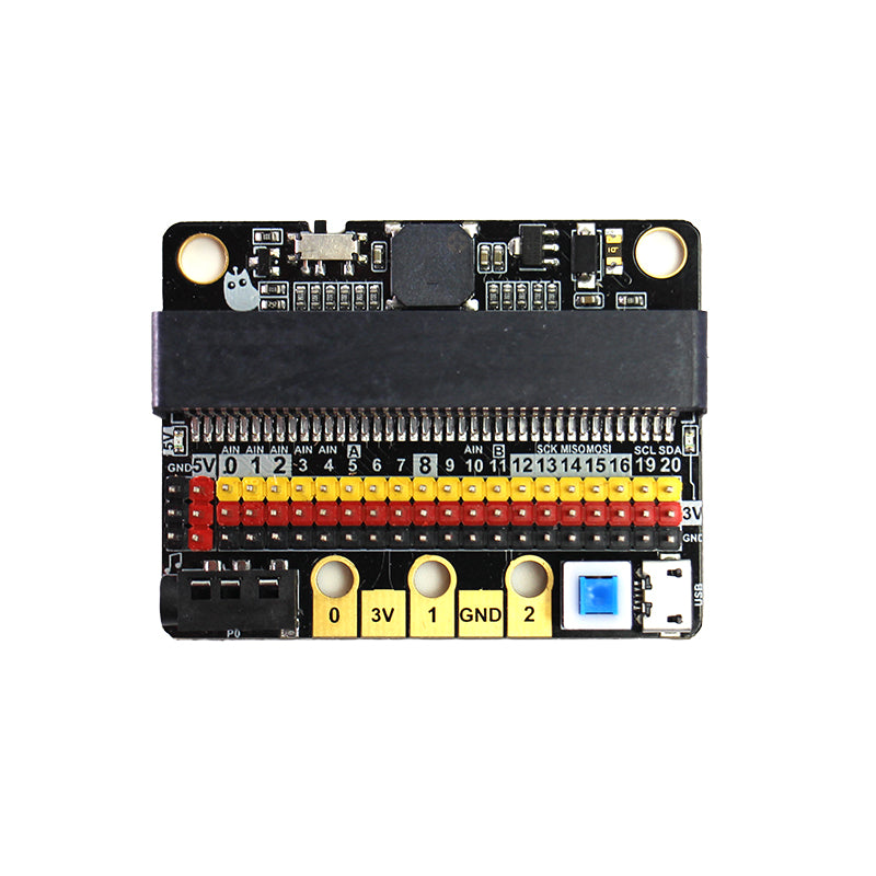
Insert the USB power supply (5V 1A) as shown in Figure 1. Press the blue button at 2, and the red indicator light at 3 will light up. You can use the left 5V interface. 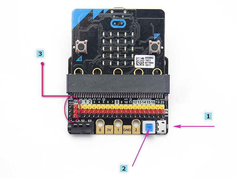
Toggle switch to turn off the buzzer function (see the silk screen on the back of the board for status) 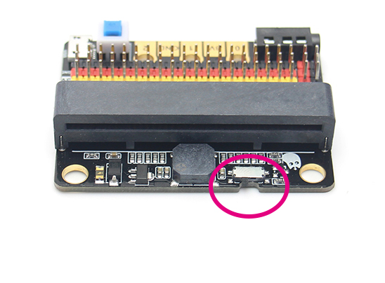
3Pin IO port leads
All the pins in the Micro:bit have been taken out without any reservation (Note: there are no P17 and P18 on the Micro:bit, it’s not that the IObit is not taken out)
Yellow corresponds to the different IO pins
Red corresponds to 3.3V/5V (with silkscreen)
Black corresponds to GND
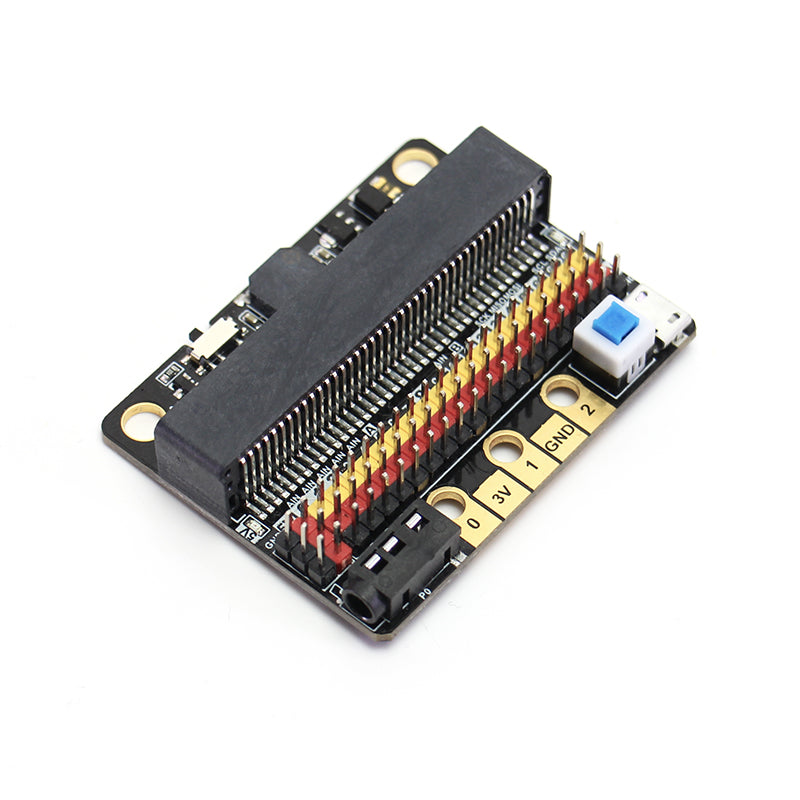
5PIN gold fingers
The gold fingers of the Micro:bit are used to draw 3v, gnd, P1, P2, and P3 respectively. This is for users who prefer to use alligator clips
Compact size socket
The two outermost holes are approximately 4.8 mm in diameter and are compatible with Lego friction pins with a spacing of 48 mm.
You can plug in a 3.5mm jack audio device and play the sound of the P0 pin.
IObit programming use:
If you haven’t gotten started with Micro:bit, first get started with Micro:bit, this is the operating premise.
Use music blocks directly in MakeCode to 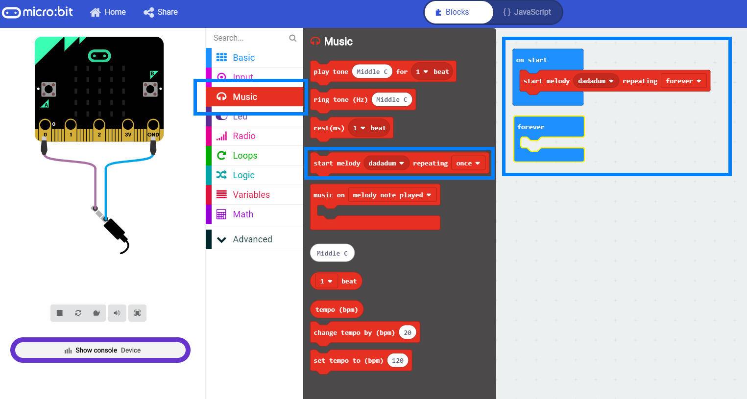
If you use P0, remember to turn the buzzer toggle switch off (because the buzzer is combined with P0)

- When using the Micro:bit power supply, IObit IO port drive capability is very weak, IO port current is less than 200mA, please do not connect high current devices (such as large servo MG995, DC motor), otherwise it will burn out the Micro:bit , you must fully understand before using what the device current conditions needed
- When using a 5V external power supply, you can drive multiple small servos, but please note that the maximum current is 1A!
-
If you use the high-low read function of the pin, you must set the pull-down on the pin.

- If P0 is used as a normal IO port, the buzzer toggle switch must be turned off, otherwise the buzzer will sound or the IO read value will be abnormal.
- Use the shared pin with the Micro:bit dot matrix (such as 3, 4, 5, 6, 7, 8, 9, 10, 11), remember to disable the dot matrix screen on the software, otherwise it will be a bit of a screen burst
- Do not use IO19, 20. 19 and 20 cannot be used as an IO port. Although the display on the MakeCode software can be used, it is actually not used! It can only be used for I2C communication
- The USB port allows a maximum input current of 1A.
- Do not place it on a metal surface to avoid short circuit
Have a question?


KittenBot IOBIT V2.0 for micro:bit